

Where the evidence overturns standard implant impression technique
Published on: 10/26/2026
A prospective clinical study of forty partially edentulous patients with two adjacent implants – the most common multi-implant scenario in general practice – found no statistically significant difference in positional accuracy between the open-tray and closed-tray implant impression techniques.1 That result runs against the accuracy hierarchy most clinicians were taught, in which open-tray is presented as the more accurate technique across the board rather than as a technique whose advantage depends on the case. It is one of several places where the evidence on implant impressions is more specific, and sometimes more permissive, than the general teaching suggests.
The stakes behind getting this right are not abstract. Every later stage of the restorative process, from working model to milled restoration, inherits whatever positional accuracy or inaccuracy the impression captured. This error does not average out through casting or digital design; it shows up at try-in as an open margin, a rocking restoration, or a screw that will not seat without forcing the implant. Several assumptions behind standard technique and material choice turn out not to hold once tested directly, and knowing which ones changes both what a given case actually needs and how much verification it warrants.
Where the evidence diverges from standard teaching
Four findings from the sections below are worth flagging before the full discussion, since each runs against a common assumption rather than confirming it.
- Open-tray and closed-tray technique perform equivalently for adjacent implants. For two adjacent, non-splinted implants specifically, the two techniques showed no significant accuracy difference in clinical testing, making closed-tray a defensible default on efficiency grounds for this specific, common case type.1
- PVS and polyether are not meaningfully different in accuracy. Material marketing often implies an accuracy hierarchy between the two; direct testing across splinted and non-splinted multiple-implant impressions found no statistically significant difference in distortion between them, leaving handling properties, not accuracy, as the deciding factor.3
Why implant impression accuracy determines the outcome of the case
A single-unit case has some tolerance for a small positional error, as the crown is not constrained by neighboring implants and can usually be seated with minor internal adjustment. A multi-unit case has none. Once two or more implants are joined by a single rigid restoration, every implant's recorded position has to agree with the position of every other implant in the same impression, or the restoration will bind on some implants and float over others when it is tried in. That condition, generally referred to as passive fit, is not a property of any single component; it is a property of the whole positional relationship between the implants as recorded in the impression and reproduced on the model.
This is why splinting, the practice of rigidly connecting adjacent impression copings or scan bodies with resin or a similar material before recording positions, has consistently outperformed unconnected copings in multi-implant cases. A systematic review of implant impression accuracy in partially and completely edentulous patients found that for completely edentulous arches, fifteen of the reviewed studies favored the splinted technique, one favored the non-splinted technique, and nine found no significant difference, with the clinical studies included uniformly favoring splinting.2 Connecting the transfer components before the position is recorded, rather than capturing each implant independently, is the more defensible default whenever more than one implant will be joined by the same restoration.
Conventional impression techniques
Conventional, or analog, implant impressions use a physical tray and an elastomeric material to capture implant position directly in the mouth. The choice of technique and material depends less on personal preference than on the number of implants involved, the angulation correction the case requires, and, as the evidence below shows, on which theoretical advantages actually hold up for a given case type.
Open-tray versus closed-tray: what actually differs
In the open-tray technique, the impression coping is secured with a guide screw that protrudes through a window in the tray and is loosened once the material sets, so the coping is withdrawn already embedded in the impression rather than repositioned afterward. In the closed-tray technique, a shorter transfer coping stays on the implant when a standard, unperforated tray is withdrawn, and the coping is then unscrewed and reseated by hand into the set material. That hand-reseating step is the main source of operator-dependent error in the closed-tray approach, which is why open-tray remains the better-justified choice for multiple implants, angled implants, and any case being splinted.
For a single pair of adjacent, non-splinted implants, though, that theoretical advantage did not translate into a measurable one. The prospective study cited above, comparing open-tray and closed-tray impressions in forty patients with two adjacent implants, found mean horizontal accuracy measurements of 9.327 mm for the open-tray group against 9.181 mm for the closed-tray group, with no significant difference in marginal discrepancy either.1 For that specific, common case type, closed-tray technique is defensible on efficiency grounds; open-tray earns its added chair time on multi-unit, splinted, and angled cases, where the mechanics of the two techniques diverge more sharply than they do on a simple two-implant span.
Selecting an impression material
Material marketing often implies an accuracy hierarchy between polyvinyl siloxane (PVS, also called vinyl polysiloxane or addition silicone) and polyether, the two elastomeric materials used for the large majority of implant impressions. A study comparing vinyl polyether silicone and polyvinyl siloxane across splinted and non-splinted open-tray techniques found no statistically significant difference in distortion between the materials, and none between the splinted and non-splinted groups within either material, with all measured groups falling within a clinically acceptable range of displacement.3 Polyether tends to be preferred where a stiffer, more tear-resistant material is useful, such as deep subgingival margins or limited interarch space, while PVS is generally preferred for its taste and shorter working and setting time. Technique and handling discipline, in other words, account for more of the final accuracy than material choice alone.
Digital implant impressions: the scan body workflow
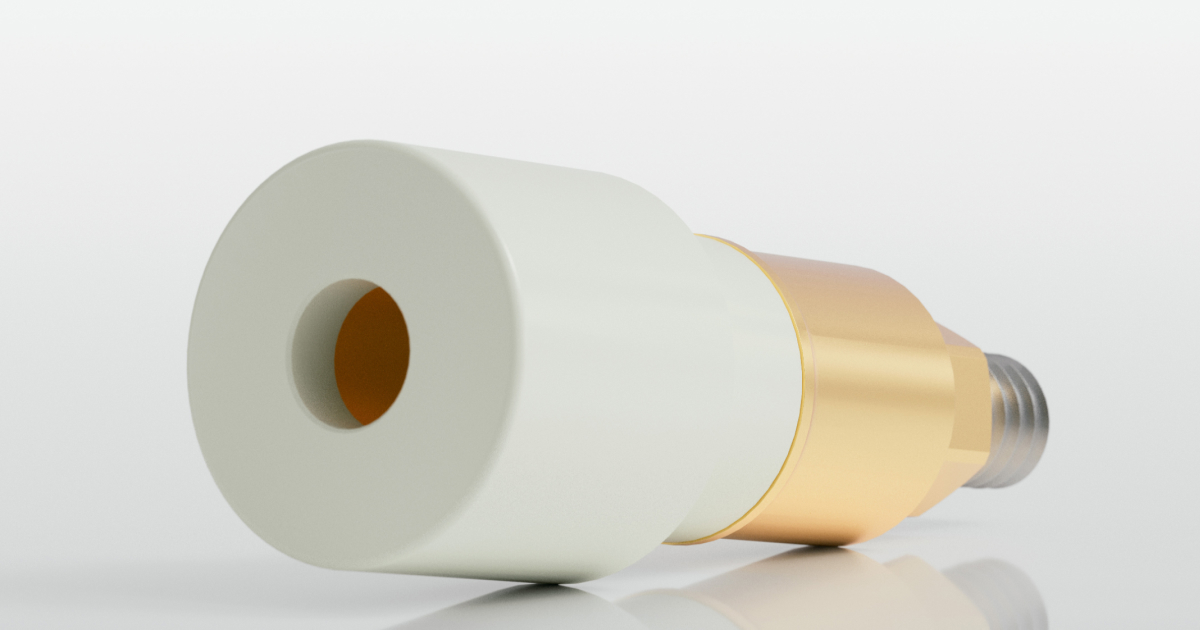
Digital implant impressions replace the tray and elastomeric material with an intraoral scanner and a scan body, a small geometric attachment that screws onto the implant platform and gives the scanner a recognizable, high-contrast shape to register and translate into implant position within the scanning software. The scan body is functionally equivalent to an impression coping in that it transfers implant position, but it does so through optical capture rather than a physical impression. In parts of the US market, the same component is sometimes called a scan body, a naming convention carried over from conventional transfer copings; the terms describe the same function, though scan body is the more widely used term internationally and is used throughout this guide.
Splinting: when it helps digital accuracy, and when it doesn't
The splinting principle established for conventional impressions does not transfer to digital scanning uniformly. A systematic review of splinted and non-splinted scan body techniques across nine studies found that splinting generally improved accuracy for complete-arch cases and reduced posterior deviation, while evidence for single-implant or short-span cases was more mixed, with several studies reporting no meaningful improvement, or even reduced accuracy, from splinting scan bodies that a stitching algorithm could already register reliably on its own.4 Rather than physically connecting copings, splinting in a digital workflow generally means stabilizing the scan bodies with a rigid connecting material, or applying a scanning strategy that stitches from one scan body to the next along a fixed path, to prevent the small positional drift that otherwise accumulates across a full arch of independently captured scan bodies. Full-arch digital scans benefit from a splinting or segmented-scanning strategy; single-unit and short-span digital scans generally do not need one.
Digital versus conventional: when scanning matches or beats a physical impression
Direct comparisons between digital and conventional full-arch implant impressions increasingly favor the digital workflow, at least at the linear accuracy thresholds that matter for restoration fit. A systematic review and meta-analysis pooling nine in vitro studies found that digital impressions achieved a mean linear accuracy of 137.86 μm, compared with 182.51 μm for conventional impressions, a statistically significant difference, with most scanner systems evaluated falling within the generally accepted clinical accuracy threshold of 200 μm.5 That result is evidence that a well-executed digital scan is not a compromise relative to a physical impression for full-arch implant cases, not a guarantee that any scan taken with any scanner will hit that threshold; scanner performance and scan body design still account for meaningful variation within the digital workflow.
What actually determines scan body accuracy
Not every scan body performs equivalently, even before scanner choice is factored in. An in vitro study testing seven scan body designs across four intraoral scanners on a full-arch model found statistically significant differences in trueness attributable to both scanner and scan body design, with the best-performing scan body design producing roughly half the three-dimensional deviation of the weakest design tested, and the best-performing scanner producing roughly half the deviation of the weakest scanner.6 Geometry mattered specifically: the top-performing designs were shorter, cylindrical shapes with a single beveled reference surface, rather than taller or more complex geometries. For a lab or clinic evaluating scan body options for a digital workflow, design consistency and manufacturing tolerance are a direct input into whether the resulting model matches the mouth closely enough to avoid a remake.
How to take an implant impression: an accuracy checklist
The steps below are not a tutorial on how to take an implant impression, a process already familiar to most clinicians and technicians; they are the points in the sequence where a positional error most often goes undetected until the restoration comes back from the laboratory and does not seat.
- Match technique to the case before defaulting to habit. Angulation, interimplant distance, and platform type determine whether an open-tray splinted technique, a closed-tray technique, or a digital scan with a splinting strategy actually fits the case, rather than reaching automatically for whichever technique is most familiar.
- Verify full seating of the coping or scan body, not just visual placement. A component seated on debris, cross-threaded, or under-torqued records a position that does not match the implant's actual position; a periapical radiograph is the standard way to confirm complete seating when tactile confirmation alone is uncertain.
- Control the intraoral field before material is dispensed or scanning begins, not during. Hemorrhage, saliva, and mobile soft tissue distort an elastomeric capture and produce noisy, unreliable optical captures alike; retraction and hemostasis addressed beforehand prevent a problem that is difficult to diagnose after the fact.
- Confirm the transfer component did not move on removal. An open-tray coping should sit visibly and rigidly embedded with no gap or rotation; a closed-tray coping must reseat by hand with a positive, verifiable click; a digital scan should show continuous, gap-free capture of each scan body with no doubling or drift in the software's real-time feedback.
- Respect the material's working, setting, and pour window, or the equivalent export timing for a digital case. Continued polymerization, moisture uptake, or an inadvertent rescan all introduce dimensional change that has nothing to do with the impression technique and everything to do with handling discipline afterward.
- Verify the result before it reaches the laboratory, not after the restoration comes back. A verification jig, radiographic check, or digital superimposition, covered below, catches a positional error while it is still cheap and fast to correct.
Common causes of distortion and remakes
Tray rigidity and coping movement
A tray that flexes on insertion or removal, from insufficient material bulk, a poor fit, or weak adhesive retention, lets the impression distort as it springs back to shape. Any undetected coping rotation within the material, even a fraction of a millimeter, carries straight into the working model and the restoration built from it.
Moisture, hemorrhage, and soft tissue interference
Blood, excess saliva, and tissue obscuring a scan body all produce incomplete or torn captures, whether the impression is analog or digital. The result is hard to catch afterward, since a distorted capture and an accurate one can look identical without close inspection.
Material handling and timing
Working time, setting time, and pour window exist because the material keeps changing dimensionally outside it. Mixing inconsistency, delayed pouring, and an incorrect stone-to-water ratio are handling errors, not technique errors, and are just as avoidable.
Angulation and non-parallel implants
A coping or scan body seated at a steep angle relative to its neighbors is harder to fully capture and more prone to shifting on removal. Splinting becomes more valuable, not less, as angulation increases, since it locks the recorded angular relationship in place rather than relying on each component independently.
Digital scanning artifacts and stitching errors
Reflective saliva, moving tissue, and inconsistent scanning speed introduce noise that a stitching algorithm can smooth over without flagging it on screen. Small errors compound across a full arch the same way positional errors compound in a splinted conventional impression.
Verifying accuracy before the lab starts work
A verification jig is a rigid structure built on the working model and then tried back in the mouth. Its fit is usually checked with the Sheffield test, also called the one-screw test: a single screw is tightened on one terminal implant, and the jig is inspected for lifting or gaps at the remaining implants. If it seats passively across all implants, without rocking or binding, the model can be trusted as an accurate reproduction of implant position. If it does not, the impression should be repeated before fabrication proceeds. For digital cases, an equivalent check can be performed by taking a second, independent scan of the scan bodies after the primary scan and superimposing the two in the scanning software; close agreement supports the accuracy of the primary scan, while disagreement beyond a clinically acceptable threshold means the case should be rescanned rather than sent forward. A periapical radiograph taken with the transfer component seated, whether at the impression stage or at try-in of a verification jig, remains a quick way to confirm complete seating before committing to a full fabrication cycle. None of these checks add meaningfully to chair time relative to the cost of a remake, and each one moves the point at which an error is caught earlier in the process, where it is cheaper and faster to correct.
Getting the impression right the first time
The technique decisions covered here are not uniformly conservative or uniformly permissive: the evidence supports moving to closed-tray for simple adjacent-implant cases and skipping scan body splinting on short spans, while just as clearly supporting splinted technique and connected scan bodies once a case becomes multi-unit or full-arch. Verification before the case leaves the chair holds its value across every scenario, however, since a positional error caught in a verification jig or a superimposed second scan costs a few minutes, and the same error caught after the restoration is milled costs a remake. Conventional and digital workflows both reach a clinically accurate result reliably when matched to the case, and the more consequential variable in most remakes traced back to the implant impression stage is not which workflow was used, but whether technique, material, and verification were matched to that case rather than applied by default.
Frequently asked questions
What improves accuracy in a full-arch digital implant impression?
Three factors have the clearest evidence: a splinting or segmented-scanning strategy to limit drift across the arch,4 a scan body with consistent, well-defined geometry,6 and a verification check before the case goes to the lab. ScanLogiQ® brings these together in a full-arch workflow that uses the clinic's existing intraoral scanner, with AssistLogiQ® validating the scan chairside in real time.
Is the closed-tray technique accurate enough for two adjacent implants?
Clinical evidence supports it for this specific case. A prospective study of forty patients with two adjacent implants found no statistically significant accuracy difference between open-tray and closed-tray techniques, provided the coping is reseated with a verifiable positive click before the impression is boxed.1
Does polyether or PVS produce a more accurate implant impression?
Neither material shows a statistically significant accuracy advantage over the other for multiple-implant impressions when handled within its working time. Polyether's stiffness suits deep margins and limited interarch space; PVS is often preferred for patient comfort and shorter setting time.3
When does a full-arch digital scan need a splinting or segmented-scanning strategy?
Full-arch cases benefit from splinting scan bodies or using a segmented scanning path, since positional drift otherwise accumulates across the arch as the scanner stitches from one region to the next. Single-implant and short-span digital scans generally do not show the same benefit from splinting.4
How does digital implant impression accuracy compare with conventional impressions for full-arch cases?
A meta-analysis of nine in vitro studies found digital impressions averaged 137.86 μm of linear deviation against conventional impressions' 182.51 μm, a statistically significant difference, with most scanner systems tested falling within the accepted 200 μm clinical accuracy threshold.5
What scan body characteristics are associated with better trueness in full-arch digital impressions?
Testing across seven scan body designs and four intraoral scanners found shorter, cylindrical scan bodies with a single beveled reference surface produced roughly half the three-dimensional deviation of taller, more complex designs, indicating that scan body geometry is a measurable, not incidental, contributor to digital impression accuracy.6
References
- Osman M, Ziada H, Suliman A, Abubakr NH. A prospective clinical study on implant impression accuracy. Int J Implant Dent. 2019;5:38. doi:10.1186/s40729-019-0190-6. pmc.ncbi.nlm.nih.gov/articles/PMC6861406
- Papaspyridakos P, Chen CJ, Gallucci GO, Doukoudakis A, Weber HP, Chronopoulos V. Accuracy of implant impressions for partially and completely edentulous patients: a systematic review. Int J Oral Maxillofac Implants. 2014;29(4):836-845. doi:10.11607/jomi.3625. pubmed.ncbi.nlm.nih.gov/25032763
- Rajendran R, Chander N, Anitha K, Balasubramanian M. Dimensional accuracy of vinyl polyether and polyvinyl siloxane impression materials in direct implant impression technique for multiple dental implants. Eur Oral Res. 2021;55(2):54-59. doi:10.26650/eor.20210110. pmc.ncbi.nlm.nih.gov/articles/PMC8244944
- Floriani F, Lopes GC, Cabrera A, Duarte W Jr, Zoidis P, Oliveira D, Rocha MG. Linear accuracy of intraoral scanners for full-arch impressions of implant-supported prostheses: a systematic review and meta-analysis. Eur J Dent. 2023;17(4):964-973. doi:10.1055/s-0042-1758798. pmc.ncbi.nlm.nih.gov/articles/PMC10756734
- Meneghetti PC, Li J, Borella PS, Mendonça G, Burnett LH Jr. Influence of scanbody design and intraoral scanner on the trueness of complete arch implant digital impressions: an in vitro study. PLoS One. 2023;18(12):e0295790. doi:10.1371/journal.pone.0295790. pmc.ncbi.nlm.nih.gov/articles/PMC10729975
Author
Rafael Saucedo
Product Manager · Digital Solutions
Drawing on more than 25 years of experience in dental technology, sales, and business development, Rafael Saucedo serves as Product Manager Digital Solutions for IPD Dental Group USA. He focuses on strengthening client relationships, enhancing sales strategies, and supporting the onboarding and training of new clients to successfully integrate IPD's technology into their clinical and laboratory workflows.
Share this content